Realizing that the nature of this work is new to some of you and that I haven’t yet explained any of the science, I figure I should give a bit of an introduction to what we’re sampling and why. So here it goes….
CTD casts
Physical oceanography’s bread and butter are salinity, temperature and density. Where many people simply see an expanse of water, a physical oceanographer envisions a complex network of currents, each with a unique signature of temperature, salinity and depth. The interaction of currents at various depths and over scales of centimeters to thousands of kilometers profoundly affects our climate; yet our understanding of ocean circulation and mixing pales in comparison to its importance for life on earth. Hence, physical oceanographers (e.g. yours truly) are tasked with keeping track of where and how the temperature, salinity and energy exchanges and moves throughout the oceans. It would be nice if satellites could answer all these questions because they sample large swaths of ocean all at once; but satellites can’t yet detect salinity and they can’t penetrate the surface of the ocean. To truly understand how currents interact and how the ocean transports heat and energy, we need to map out changes in temperature, salinity and density over both space and time; hence the need for what is called a CTD cast.
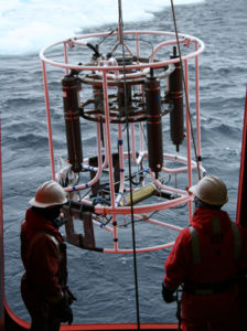
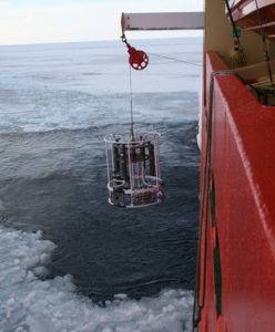
The term CTD is generically used to describe a sampling routine that is often much more encompassing than the acronym for “Conductivity”, “Temperature”, and “Density” would imply. (For all intents and purposes, conductivity can be thought of as salinity, which is what the measurement is used to gauge.) While there is a CTD instrument that we depend on to detect temperature and salinity, we usually use the term CTD in reference to a circular, metallic skeleton that hosts the CTD instrument and other sampling tools in a frame that is approximately 2m in diameter and height. The CTD instrument is only a small fraction of the entire outfit, the bulk of which is occupied by twenty-five 1 m. long sampling tubes called “Niskin bottles.” A Niskin rosette may be the more accurate term to describe the apparatus on which the CTD is mounted, but science slang is simply “CTD”.


On its way down, the CTD transmits information up the line for us scientists to observe the water below. Each, meter-long Niskin bottle opens at the ends so that water passes through the tubes as the rosette descends. Using the CTD information, we trigger the Niskin bottles (usually one at a time) to close at various depths, trapping water to sample depending on the type of information that we seek.
Other instruments are also lashed onto the rosette. Upward and downward looking current meters yield information on current speeds, a particle density instrument tells us how much “stuff” is in the water, and a camera shows us what that stuff is. To prevent a crash landing on the sea floor, we turn on “the machine that goes ping”. The signal from this sonar transmitter will be recorded by the ship’s receiver to gauge the distance of the CTD below the ship. Meanwhile, the ship’s sonar, which I listen to from my bunk as I go to sleep, is used to approximate the bottom depth. We know when the CTD is nearing the bottom when the CTD’s distance from the ship is nearly equal to the depth recorded by the ship’s sonar; but because sound moves at different speeds through the different density layers, the sonar depth reading isn’t always accurate. To prevent this expensive equipment from hitting the bottom, a weighted line dangles 10 meters below the CTD and will trip an alarm in the control room when it hits ground.
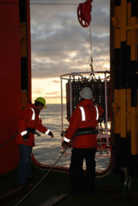
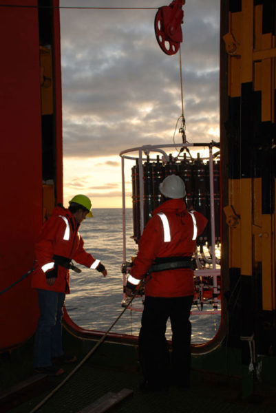
Now you have enough information to envision the scene during CTD casts. Some people don hard hats and orange safety coats (float coats) to circle the rosette, check lines, and turn on instruments; others gather in a cubby of computer monitors and screens, reading the active lines and waiting for signals. Radios chirp on and off as the bridge communicates about positioning, the winch operator signals preparedness and the computers are confirmed to be working. Then the side of the hull is opened to expose a gaping hole through which a boom moves the rosette out of the ship and into the sea.

Rachael (left) and Jeremy Lucke (right) bringing in the CTD.
Once the water from a CTD cast is brought onboard, a flurry of activity ensues and the water is in high demand. For a biologist, water samples help to identify the amount and/or type of living organisms in the water column. On our cruise, we are primarily using the water to understand the age and origin of the various currents. The first samples that we take from the Niskin bottles are for measurements of Sodium Hexaflouride (SF6) and CFCs, followed by dissolved oxygen and nutrients, and finishing with salinity samples that will be analyzed onboard to help calibrate the CTD’s conductivity measurement.
CFCs and SF6
CFCs and SF6 are sampled to determine “the age” of water. Young water has had recent been in contact with the surface (atmosphere) while old water has been insulated from the atmosphere and has changed in character only through circulation and biological feedbacks. These man-made chemical tracers can only be introduced to the ocean by the atmosphere or by injection, so the concentration of these chemicals provides clues to when the water was last in contact with the source. For example, CFCs where first introduced to the atmosphere in the 1950s and increased in concentrations until the mid 1990s. When water is at the ocean’s surface it incorporates the CFC signature of the atmosphere at that time and thus provides a time stamp for when the ocean last contacted the atmosphere. Until recently, SF6 wasn’t in high enough atmospheric concentrations to use in this manner. Instead, it was injected into the ocean (as an inert tracer) and then used to investigate circulation pathways. On this cruise, we are experimenting with the use of SF6 as an atmospheric tracer (like CFCs) and are testing whether oceanography can make use of the increased SF6 levels to deepen our knowledge of ocean circulation.
Oxygen
Oxygen samples offer a variety of information, from biological productivity to the ocean’s contact with ice shelves. We want to know how much dissolved oxygen there is and what the oxygen isotopes are. An increase in dissolved oxygen at certain depths can reflect a layer of melted ice shelf water in which the air bubbles that were trapped in the ice were released upon melting to contribute higher dissolved oxygen levels than the ambient values. The two kinds of oxygen isotopes that we measure (oxygen-16 and -18) can also reveal information about the water origin; but interpreting the oxygen isotope ratios is tricky business because different processes (e.g. contact with ice shelf, surface snow or freezing ice) can similarly affect the isotope ratio. As is often the case in science, we need to employ multiple techniques to allow us to more fully and accurately interpret results.
